
Checklist Before Submitting an RMA Request
Based on prior experience, a short troubleshooting session may reveal the root cause of a failure and prevent redundant shipment of parts.Dragon Well provides the below checklists for common issues of our products, and updates the checklists regularly, based on our customers' feedback and our continued experience.
Dragon Well Fiber Optic Transceiver Diagnostic Checklist
Step 1: Physical Connection Verification
➠ Action:
Re-seat transceiver firmly into the device port.
Confirm audible click indicating full insertion.
Step 2: Configuration Cross-Check
| Parameter | Transceiver A | Transceiver B |
|---|---|---|
| Type (e.g., SFP28) | Must match | Must match |
| Data Rate | Must match | Must match |
| Wavelength | Must match | Must match |
| Port Settings* | Identical | Identical |
| *Includes FEC, Auto-negotiation, Duplex Mode |
➠ Cable Compatibility:
Single-mode fiber ↔ 1310/1550nm transceivers
Multi-mode fiber ↔ 850nm transceivers
DAC/AOC cables ↔ Matching interface types
Step 3: Device Interface Diagnosis
➠ Procedure:
Access device CLI/GUI (e.g.,
show interfaces).Check for error flags:
RX Loss/TX FaultModule Not Supported
Critical Alert:
"UNSUPPORTED TRANSCEIVER"= Compatibility issue
Step 4: DDM Parameter Validation
Acceptable Ranges:
| Parameter | Min | Max |
|---|---|---|
| Temperature | -5°C | +75°C |
| Voltage | 3.13V | 3.47V |
| TX Power | See datasheet | |
| RX Power | > Receiver sensitivity | |
| ➠ Note: Copper RJ45 & Media Converters lack DDM. |
Step 5: Optical Signal Troubleshooting
Link Loss Budget Formula:
Maximum Allowable Loss (dB) = TX Power (dBm) - Receiver Sensitivity (dBm)
Debug Sequence:
Clean: Use LC/SC fiber cleaner on transceiver ports & cable ends.
Test: Measure end-to-end loss with optical power meter.
Swap:
Try known-working port on same device
Replace with same Dragon Well P/N from original order
Use verified optical cable
Diagnostic Flow: Port Insertion → Configuration → Signal Verification
DAC & AOC Cable Checklist
1. If the DAC & AOC cable isn’t recognized by the switch or link’s errors, plug and unplug the cable again, and make sure that it is correctly inserted into the port of the designated device.
Check whether the 40G or 100G port is configured as Breakout mode.
- Repeat the test after plugging the cable into another known working port.
- Repeat the test after replacing other cables with the same P/N from the same Dragon Well order.
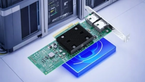
Network Interface Card Checklist
1. If the card isn’t recognized by the OS, reseat the card in the server PCI slot, and verify that the card is recognized by the OS.
- In Linux based OS: lspci | grep –i net
- In Windows OS:
Under “Device Manager-> Network Adapter”, check it. If you cannot find the network card, click “Action-> Scan for hardware changes”.
2. Verify that the card driver version is up to date. If not, please install the latest version.
3. Please use a known working cable to connect network card and switch, verify the physical connectivity, and check whether the port works normally.
Note: Read ports LEDs indication – Is it in a faulty state? (A stay-on green light means normal.)
4. Communication test, please use the known working cable to connect network card and switch, then test in the same leaf.
5. Repeat the test after replacing another known working network card.
Note: If the issue recurs with the known working card, it is most likely that the network card bought is not faulty.
Network Switch Checklist
Switch Power Supply and Fan FRU (Field Replacement Unit) Checklist
Are the LEDs indicating a faulty state?
- For S58xx Series Switch:
Switch#show environment—Check the running state
- For Nxxxx Series Switch:
Cumulus@switch:~$ sudo smonctl—View sensor information for various system units
Cumulus@switch:~$ sensors—Check the running state of the hardware
3. Replace another available power supply and PDU, and exchange a known working FRU with the defective FRU for testing.
4. Read the power/fan LED indicator, and check if the indicator is stay-on green.
5. Repeat the test in STEP2. to verify if the FRU module is working normally.
Log In Checklist
1. If you encounter a problem that you cannot log in to the switch by using the console cable, please perform the following:
- Verify that the computer has installed the driver successfully. Then the corresponding communication port (COM X) can be seen under the device manager > port option after the console cable is plugged into the computer.
- Verify that the console cable is properly connected to the switch console port.
- Set the correct parameters on SecureCRT, refer to the following:
- Replace the connected console cable with another known working cable, and verify whether you can log in with the working cable.
- Verify whether the control software is working well. Putty or Xshell is recommended by FS.
2. If you encounter a problem that you cannot log in to the switch remotely through the admin port or plain port, please perform the following:
- Please confirm whether the switch management port IP address, vlanif IP address and PC IP address can be pings normally. It is recommended to directly connect the switch and PC for ping test.
- Replace the network cable with another known working cable to connect the switch and the PC.
- Ensure whether the switch has HTTP, HTTPS, Telnet, and SSH enabled.
- Try changing the browser to login.
Ports Checklist
1. If you encounter problems with ports not working properly, please perform the following:
- Replace the connected cables with another known working cable.
- Connect the cables to another known working port.
- Check the port configuration to see if the port is activated. If not, please activate the port by invoking the command: no shutdown.
- Perform a loopback test by connecting the faulty ports to another known working port in the same leaf.
- Read ports LEDs indication. Check if the LED indicator is stay-on green.
- Please perform the communication testing: Connect two switches with a working cable, then configure the ports of both switches to the same network segment for testing.
2. If the cable or transceiver is not working because the date rate of the port doesn’t match, please perform the following:
- Verify the cable or transceiver has the same data rate with the ports.
- Note: if the cable or transceiver data rate is 1G while the switch port is 10G, it is recommended to set the port of 10G switch to 1G rate mode and then perform the test again.
- Perform a loopback test to ensure there is no incompatibility problem.
- Read ports LEDs indication. Check if the LED indicator is stay-on green.
Mux Demux & OADM Checklist
- Single/Dual Fiber CWDM MUX/DEMUX
- Single/Dual Fiber CWDM MUX/DEMUX
- Single/Dual Fiber CWDM OADM
- Single/Dual Fiber CWDM OADM
Monitor Online Software Checklist
If the localhost IP can be pinged, check whether the server name format of the SQL Server database is the same as the localhost address, or you can copy the server name content in the SQL Server database to the localhost address directly.
FMT Pluggable Module Checklist
- Check whether the Power and Run lights of the Pluggable Module are normal.
- Use Monitor Online Software and Simple Management Tool for login Management to check whether the Pluggable Module information can be monitored.
- Check whether the Pluggable Module information can be viewed on the display screen of the NMU main control card.
- Re-insert the defective Pluggable Module or re-start the Fiber Enclosure for testing.
- Place the defective Pluggable Module into other card slots of the Fiber Enclosure to see if it can be monitored.
- Place the defective Pluggable Module into other Fiber Enclosures to see if it can be monitored.
- Check if the indicator light on the Pluggable Module is red.
- Use Monitor Online or Simple Management Tool to manage and read the Monitor information on the Pluggable Module interface to see if the information is abnormal.
- If it is an input-output alarm, connect the input side light of the Pluggable Module to the optical power meter to check whether the input optical signal is normal.
- If it is EDFA Pluggable Module, check whether the Pump light source of EDFA is turned off.
- Repeat the test after replacing other items with the same P/N from the same Dragon Well order.
- Use the module on the switch to see if the module can function well.
- After inserting the module, observe whether the indicator light below the corresponding port of the OEO Pluggable Module is always on.
- Check whether the module information can be monitored on the display of the Simple Management Tool, Monitor Online, and NMU main control card.
- Use the defective module in other good combination ports of the OEO Pluggable Module to see if it can be monitored.
- Place the defective module on other OEO Pluggable Modules to see if it can work normally.
Fiber Optic Patch Cable Checklist
Fiber Cassette & Enclosure Checklist
You may learn more about regular connection and polarity.