Decoding RJ45 Terminology: Connector Wiring vs. Plug Connection Diagrams
In Ethernet networking, understanding the distinction between RJ45 Connector Wiring Diagrams and RJ45 Plug Connection Diagrams is fundamental to proper network implementation. While these terms are often used interchangeably, they represent fundamentally different concepts with distinct applications in network infrastructure. A RJ45 Connector Wiring Diagram typically illustrates the internal pin-to-pin connections within jacks, ports, or surface mount boxes, while a RJ45 Plug Connection Diagram demonstrates how individual wires should be arranged and terminated into modular plugs for cable assembly. This comprehensive guide explores both methodologies, their appropriate applications, and the technical implications of each approach.
Understanding the Physical Components: Connectors vs. Plugs
Rj45 Connector Wiring Diagram Architecture: The Fixed Interface Standard
The term “connector” in formal networking terminology typically refers to the female jack interface permanently installed in wall plates, patch panels, or device ports. These components feature:
- Fixed Pin Assignments: Internal contacts arranged according to T568A or T568B standards
- Punch-Down Termination: IDC (Insulation Displacement Connector) blocks for solid conductor wires
- Permanent Installation: Designed for infrastructure wiring with minimal reconfiguration
- Manufacturer-Specific Layouts: While following standards, internal routing may vary by brand and design
RJ45 Plug Construction: The Modular Cable Solution
RJ45 plugs represent the male components crimped onto cable ends, characterized by:
- Modular Design: Standardized 8P8C (8 position, 8 contact) configuration
- Crimp-Style Termination: Metal contacts that pierce conductor insulation when compressed
- Transient Application: Designed for frequent connection and disconnection cycles
- Universal Compatibility: Generally interchangeable across manufacturers when quality standards are maintained
Comparative Analysis: Connector Wiring vs. Plug Connection Methodologies
Purpose and Application Context
The fundamental difference between these diagram types lies in their application:
- RJ45 Connector Wiring Diagrams guide permanent infrastructure installation
- Wall jack termination in commercial buildings
- Patch panel configuration in data centers
- Device port manufacturing and repair
- Keystone jack installation in structured cabling
- RJ45 Plug Connection Diagrams direct cable assembly processes
- Patch cable fabrication for network connectivity
- Equipment cable manufacturing
- Field termination of bulk cable runs
- Custom-length cable creation for specific applications
Technical Execution Differences
The physical implementation varies significantly between these termination types:
| Aspect | RJ45 Connector Wiring | RJ45 Plug Connection |
|---|---|---|
| Termination Method | Punch-down tool with impact mechanism | Crimping tool with die-specific jaws |
| Conductor Type | Solid core (0.5-0.65mm) preferred for stability | Stranded (0.2-0.4mm) preferred for flexibility |
| Strain Relief | Integrated into housing design | Provided by crimp tool deformation and boot |
| Re-termination | Limited (2-3 cycles typically) | Single-use (contacts permanently deformed) |
| Tool Investment | Moderate ($30-100 for punch-down tool) | Low to moderate ($20-80 for crimper) |
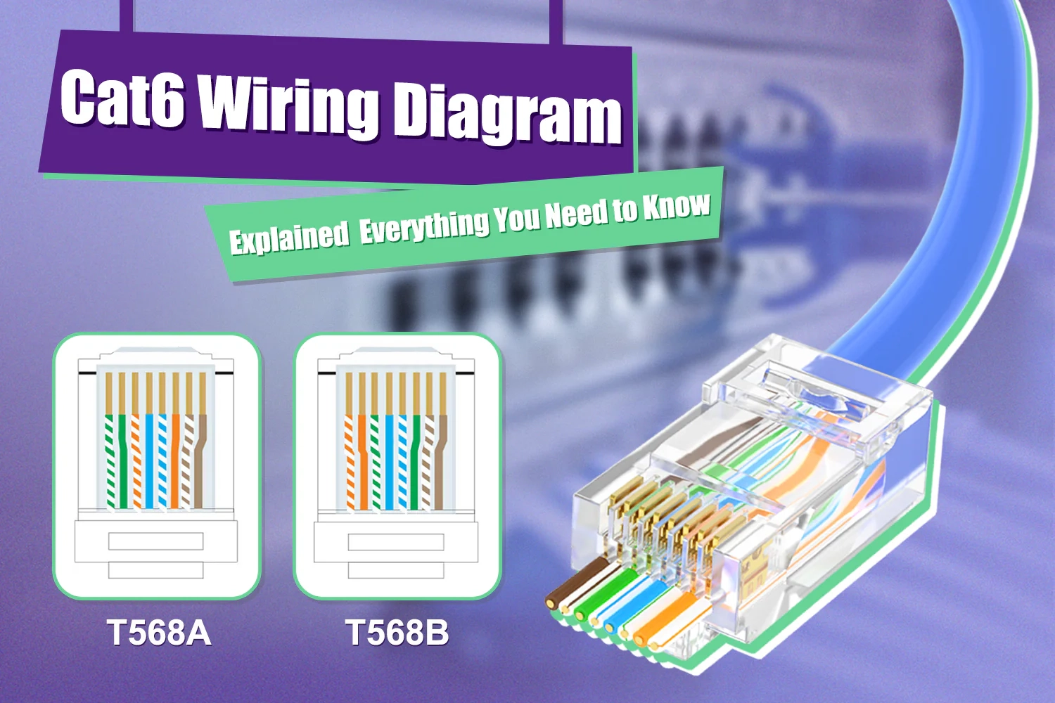
Wiring Standards: T568A vs. T568B Configuration
Historical Context and Regional Preferences
Both connector and plug diagrams must adhere to established TIA/EIA-568 standards:
- T568A Configuration:
- Preferred in residential and government installations
- Maintains backward compatibility with USOC telephone wiring
- Pinout: White/Green, Green, White/Orange, Blue, White/Blue, Orange, White/Brown, Brown
- T568B Configuration:
- Dominant in commercial installations and manufacturing
- Better isolation between transmit and receive pairs
- Pinout: White/Orange, Orange, White/Green, Blue, White/Blue, Green, White/Brown, Brown
Technical Implications of Standard Selection
The choice between T568A and T568B has measurable performance consequences:
- Crosstalk Performance: T568B provides slightly improved near-end crosstalk (NEXT) protection
- Pair Utilization: Both standards use pairs 2 (orange) and 3 (green) for data transmission in 10/100BASE-T
- Gigabit Ethernet Compatibility: Both standards fully support 1000BASE-T using all four pairs
- Infrastructure Consistency: The critical requirement is maintaining one standard throughout a installation
Advanced Wiring Configurations: Beyond Standard Straight-Through
Crossover Cable Implementation
Specialized applications require deviation from standard pinouts:
- Traditional Ethernet Crossover:
- Direct connection between similar devices without switches
- Transmit and receive pairs swapped at one end
- Uses T568A at one end, T568B at the other
- Auto-MDIX Technology Impact:
- Modern equipment automatically detects and compensates for crossover needs
- Reduced necessity for specially-wired cables
- Maintains relevance for certain legacy equipment and specific applications
Specialized Industrial Applications
Harsh environments demand modified approaches:
- Industrial Ethernet Protocols (Profinet, EtherCAT):
- Often require specific shield termination methods
- May utilize alternative pin assignments for power delivery
- Frequently employ ruggedized connectors with enhanced locking
- Power over Ethernet (PoE) Considerations:
- Standard PoE (802.3af/at): Uses data pairs (Mode A) or spare pairs (Mode B)
- Ultra PoE (802.3bt): Utilizes all four pairs for power transmission
- Connector wiring must maintain pair integrity to prevent power delivery issues
Performance Optimization: Signal Integrity Considerations
Maintaining Pair Twist for Noise Immunity
Proper wiring technique significantly impacts network performance:
- Untwist Length Limitations:
- Category 6: Maximum 13mm (0.5″) untwisted at termination
- Category 6A: Maximum 10mm (0.4″) untwisted at termination
- Excessive untwisting causes impedance discontinuities and return loss
- Pair Separation Philosophy:
- Differential signaling relies on tight pair coupling
- Cross-talk between pairs increases with separation distance variation
- Consistent termination technique critical for performance certification
Shielding Considerations in Connector Installation
Proper shield termination prevents ground loops and maintains EMI protection:
- F/UTP (Foiled Twisted Pair):
- Drain wire must connect to connector shield
- Foil shield must maintain continuity through connection point
- Grounding must follow single-point reference principles
- S/FTP (Shielded Foiled Twisted Pair):
- Individual pair shields plus overall braid shield
- Complex termination requiring specialized connectors
- Critical for high-noise industrial environments
Troubleshooting Common Termination Issues
Connector Wiring Failure Patterns
Frequent problems in jack and port installation:
- Punch-Down Tool Misapplication:
- Insufficient force failing to penetrate conductor insulation
- Excessive force damaging IDC contacts or conductor
- Incorrect blade orientation cutting conductors
- Conductor Preparation Errors:
- Insufficient jacket removal causing binding in wire guides
- Excessive jacket removal reducing strain relief effectiveness
- Crossed conductors between termination points
Plug Connection Failure Modes
Common issues in modular plug termination:
- Wire Sequencing Errors:
- Misordering during insertion into plug
- Incomplete insertion causing poor contact penetration
- Pair separation exceeding category specifications
- Crimping Process Deficiencies:
- Incomplete crimp cycle leaving contacts partially engaged
- Over-crimping deforming plug housing and damaging contacts
- Misaligned dies causing uneven contact penetration
Testing and Verification Methodologies
Continuity Testing vs. Performance Certification
Different validation approaches for various installation phases:
- Basic Continuity Verification:
- Simple wire map testers confirm pin-to-pin connectivity
- Detect opens, shorts, and miswires
- Inexpensive solution for basic functionality confirmation
- Performance Certification:
- Tiered approach (Level I, II, III, IV) with increasing accuracy
- Measures insertion loss, return loss, near-end and far-end crosstalk
- Required for installation warranty validation
Troubleshooting with TDR Capabilities
Time Domain Reflectometry applications in wiring diagnosis:
- Fault Location Precision:
- Distance-to-fault measurement with 1-2% accuracy
- Identifies crimp defects, conductor damage, and impedance anomalies
- Essential for troubleshooting installed infrastructure
- Performance Margin Analysis:
- Identifies links operating near specification limits
- Predictive maintenance for potential future failures
- Documentation for infrastructure quality assessment
Future Trends: Emerging Standards and Technologies
Category 8 and 2000MHz Performance Requirements
Next-generation cabling demands enhanced termination precision:
- Reduced Tolerance Margins:
- Category 8 specifications require near-perfect termination
- Minimal untwist length (≤8mm) for 2000MHz operation
- Precision connectors with improved return loss characteristics
- Shielding Becomes Mandatory:
- Alien crosstalk prevention requires full channel shielding
- Shield continuity essential for performance compliance
- Specialized tools for consistent shield termination
Modular Plug Linked Segment (MPLS) Evolution
Field-terminated plug standardization efforts:
- Performance-Equalized Plugs:
- Integrated compensation for plug-induced signal distortion
- Required for meeting higher category performance standards
- Manufacturer-specific compatibility considerations
- Tooling Evolution:
- Automated termination systems for consistency improvement
- Guided assembly processes reducing technician skill requirements
- Integrated testing during termination process
Best Practices Summary: Ensuring Installation Success
Documentation and Labeling Standard
Consistent implementation prevents future confusion:
- Diagram Standardization:
- Maintain consistent diagram usage throughout organization
- Document exceptions and special configurations thoroughly
- Update documentation with any infrastructure modifications
- Physical Identification:
- Color coding for different applications or standards
- Clear labeling of termination standard used (T568A/B)
- Permanent identification resistant to environmental factors
Quality Assurance Processes
Systematic approaches to termination excellence:
- Sample-Based Verification:
- Test first and last termination of each production run
- Statistical sampling for high-volume installation
- Documentation of test results for quality tracking
- Continual Technician Training:
- Regular refresher training on proper techniques
- Certification programs for critical infrastructure
- Cross-training on multiple connector systems
Understanding the nuanced relationship between RJ45 Connector Wiring Diagrams and RJ45 Plug Connection Diagrams enables network professionals to select the appropriate methodology for each application. By recognizing that connector diagrams guide permanent infrastructure installation while plug diagrams direct cable assembly processes, technicians can implement more reliable, higher-performing network infrastructures. As network speeds continue to increase toward 40GBASE-T and beyond, termination precision becomes increasingly critical, making proper diagram interpretation and implementation essential skills for any network professional.