
Understanding the Connectors: GX16 vs. RJ45 Fundamentals
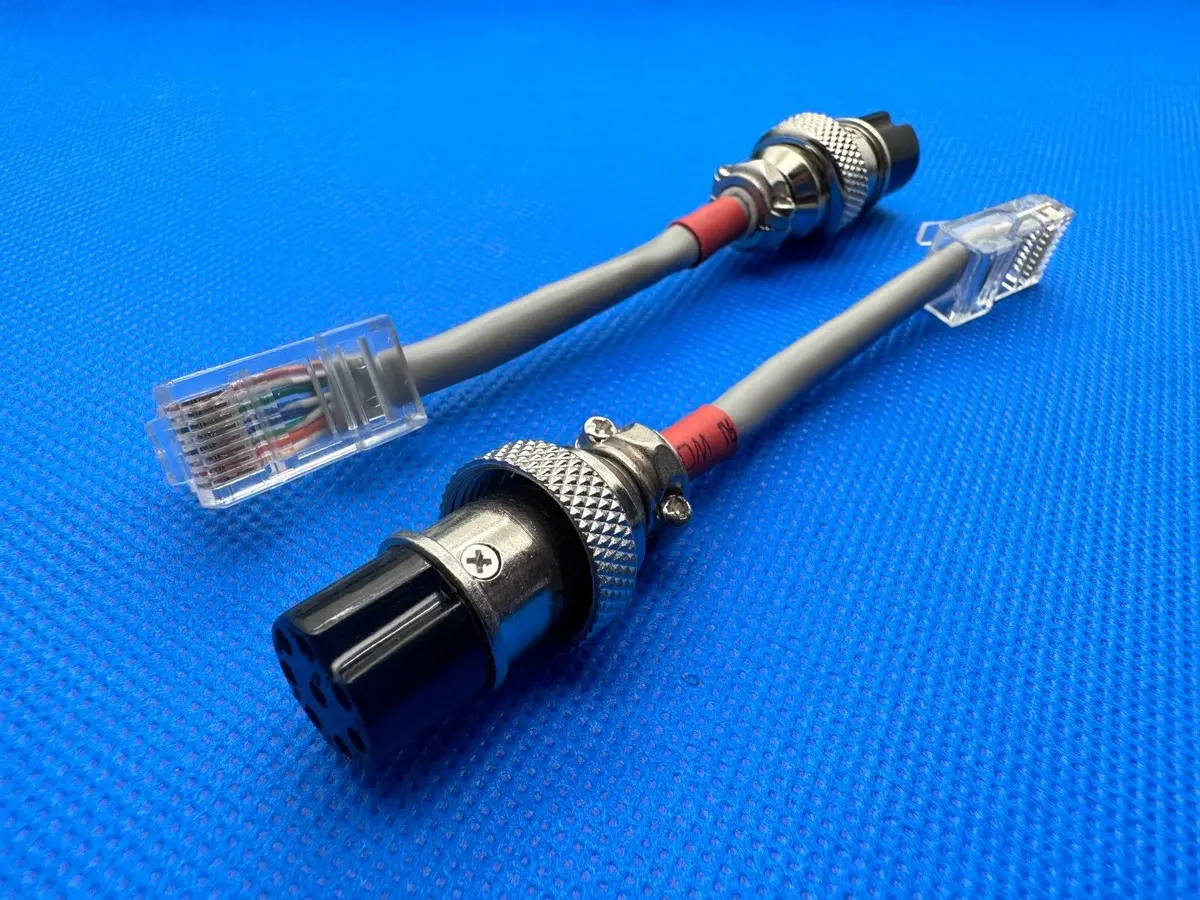
- The GX16 Circular Connector:
- Design: A robust, threaded, circular connector standardized under IEC 61076-2-106. The “GX” denotes a specific shell size (16mm diameter), followed by a pin count (e.g., GX16-3 = 3 pins, GX16-5 = 5 pins, GX16-8 = 8 pins).
- Key Features: Metal shell (typically brass or aluminum, often nickel-plated), screw-locking mechanism for vibration resistance, IP-rated variants available for dust/water resistance (e.g., IP67), solder cup or crimp pin/socket contacts.
- Applications: Aviation, industrial automation (robotics, sensors, actuators), professional audio/video equipment, medical devices, military hardware – anywhere requiring a secure, reliable connection in harsh environments.
- The RJ45 Modular Connector:
- Design: The ubiquitous 8P8C (8 Position, 8 Contact) connector standardized for Ethernet (IEEE 802.3) and telecommunications.
- Key Features: Plastic housing, gold-plated contacts, designed for twisted pair cabling (Cat5e, Cat6, etc.), latch mechanism for secure connection, standardized T568A/B wiring schemes.
- Applications: Computer networking (LAN/WAN), VoIP phones, PoE devices, industrial Ethernet (Profinet, EtherCAT), serial communications (RS-232 over RJ45), building automation.
Why Convert GX16 to RJ45? Key Applications & Use Cases
Converting GX16 to RJ45 bridges the gap between rugged field devices and standardized network/comms infrastructure:
- Industrial Ethernet Integration: Connecting sensors, actuators, HMIs, or PLCs using GX16 ports to Ethernet-based control networks (e.g., Profinet, EtherNet/IP, Modbus TCP) via RJ45 jacks on switches or controllers.
- Professional Audio/Video (Pro AV): Interfacing broadcast cameras, microphones, intercom systems, or lighting controllers with GX16 outputs to AoIP (Audio over IP – Dante, AES67) or video-over-IP networks using RJ45.
- Aviation & Ground Support Equipment (GSE): Linking aircraft components (data loggers, sensors) or GSE test sets with RJ45 ports on diagnostic laptops or network recorders.
- Robotics & Motion Control: Connecting servo drives or motor controllers (using GX16) to centralized controllers or EtherCAT masters via RJ45.
- Custom Device Interfacing: Adapting specialized equipment (medical devices, test instruments) with GX16 ports to standard network analyzers or PCs.
Key Driver: The need for ruggedized RJ45 connectivity where standard plastic RJ45 plugs would fail due to vibration, moisture, dust, or frequent mating cycles.
Critical Considerations Before Wiring
- H3: Pin Count & Purpose:
- Identify GX16 Pin Count: Is it GX16-3, GX16-4, GX16-5, GX16-6, or GX16-8? This is paramount. A GX16-5 cannot magically become a full 8-conductor RJ45.
- Define the Signal Path: What signals/protocols are being carried? Ethernet? RS-232/422/485? Analog Audio? Power (PoE)? Control signals? Each dictates wiring needs.
- H3: Protocol & Wiring Standards:
- Ethernet: Requires specific twisted pairs (T568A/B standard) for optimal performance and noise immunity. Using random pin mapping causes crosstalk, signal loss, and link failures.
- RS-232/422/485: Typically uses only 3-5 conductors (Tx, Rx, GND, +/- for 422/485). Pinout varies by device.
- Analog Audio: Often unbalanced (Tip/Sleeve) or balanced (Tip/Ring/Sleeve per channel). Needs shielding consideration.
- PoE (Power over Ethernet): Requires using specific pairs (Mode A: Pins 1-2+/3-6- or Mode B: Pins 4-5+/7-8-) and compatible voltage/current ratings on both GX16 pins and cable.
- H3: Cable Specifications:
- Type: Shielded Twisted Pair (STP/FTP) is essential for Ethernet, RS-485, and analog signals in noisy environments. Avoid UTP.
- Category: Cat5e minimum for 1Gbps Ethernet. Cat6/6a for higher speeds or longer runs (>55m).
- Conductor Gauge: 24-26 AWG is standard. Ensure GX16 contacts can handle the gauge.
- Jacket: Choose PVC for general use, PUR for oil/flex resistance, or PE for outdoor/UV resistance.
GX16 to RJ45 Wiring Configurations & Pinouts
There is NO universal standard. Wiring depends entirely on the GX16 device’s function and the target protocol.
Common GX16 to RJ45 Pin Mapping Scenarios:
| GX16 Pin | Typical Function (Example) | RJ45 Pin (T568B) | RJ45 Wire Color (T568B) | Critical Consideration |
|---|---|---|---|---|
| 1 | Shield/Drain Wire | Cable Shield | N/A (Braid/Foil) | Must connect to GX16 shell & RJ45 plug shield |
| 2 | RS-485 Data+ / PoE+ | 4 | Blue/White | Use twisted pairs for differential signals |
| 3 | RS-485 Data- / PoE- | 5 | Blue | Paired with Pin 2 |
| 4 | RS-485 GND / Analog GND | 7 | Brown/White | Common reference point |
| 5 | +12V / +24V (PoE) | 8 | Brown | Verify voltage/current compatibility |
| 1 | Ethernet Tx+ | 1 | Orange/White | Must use T568A/B pairs |
| 2 | Ethernet Tx- | 2 | Orange | Paired with Pin 1 |
| 3 | Ethernet Rx+ | 3 | Green/White | Paired with Pin 6 |
| 6 | Ethernet Rx- | 6 | Green | Paired with Pin 3 |
| 4 | PoE+ (Mode B) / Unused | 4 | Blue/White | |
| 5 | PoE- (Mode B) / Unused | 5 | Blue | |
| 7 | Shield | Shell/Shield | N/A | |
| 8 | Unused / Reserved | – | – |
Application-Specific Wiring Notes:
- Full Ethernet (GX16-8): Use pairs: (1-2), (3-6), (4-5), (7-8). Follow T568B strictly. Connect shield.
- Industrial Ethernet (e.g., Profinet w/ GX16-4): Often uses Pins 1-2 (Tx), 3-6 (Rx), 4-5 (PoE+), 7-8 (PoE-). Map GX16 pins accordingly.
- RS-485 (2-wire + GND w/ GX16-3): Pin1: Data+, Pin2: Data-, Pin3: GND. Map to RJ45 pins respecting pair integrity (e.g., 4-5 or 3-6).
- Analog Audio (Balanced, per channel w/ GX16-5): Pin1: Ch1+, Pin2: Ch1-, Pin3: Ch1 GND, Pin4: Ch2+, Pin5: Ch2-. Map to RJ45 pairs (e.g., 1-2 & 4-5). Shield connected.
- PoE Only (GX16-2/3): Pins: +V, -V, (Optional GND). Map to RJ45 Mode A (1-2+ & 3-6-) or Mode B (4-5+ & 7-8-). Verify voltage/current!
Step-by-Step: Building a Reliable GX16 to RJ45 Cable
Tools & Materials Required:
- GX16 Plug/Socket (Correct gender & pin count)
- RJ45 Plug (Shielded type recommended)
- Shielded Ethernet Cable (Cat5e/Cat6, appropriate length)
- Wire Strippers / Coax Stripper
- Precision Screwdrivers
- Soldering Iron & Solder (or Crimp Tool if using crimp contacts)
- Heat Gun & Adhesive Heat Shrink Tubing (various diameters)
- Multimeter / Cable Tester
- Pinout Diagram (Device/Application Specific!)
Assembly Procedure:
- Prepare Cable Ends:
- Cut cable cleanly. Strip ~50mm outer jacket, exposing inner pairs and shield drain wire. Avoid nicking inner conductors.
- Unwind shield braid/foil neatly. Fold back over outer jacket. Trim foil if present.
- Strip ~7-8mm insulation from each required inner conductor.
- Terminate RJ45 Plug (T568B Standard Recommended):
- Untwist pairs minimally (<12mm). Arrange conductors in T568B order: Orange/White, Orange, Green/White, Blue, Blue/White, Green, Brown/White, Brown.
- Trim ends evenly. Insert firmly into RJ45 plug until wires hit the end. Verify order through plug.
- Crimp firmly using shielded RJ45 crimper. Ensure contacts pierce conductors and strain relief crimps onto jacket/shield.
- Terminate GX16 Connector:
- Strain Relief: Slide large heat shrink and/or cable gland nut onto cable.
- Shield Connection: Solder drain wire to GX16 shell’s dedicated solder tab. If none, solder to a dedicated shield pin.
- Conductor Termination:
- Solder Cups: Tin wire ends lightly. Insert into cup. Apply soldering iron to cup, allowing solder to flow. Avoid cold joints.
- Crimp Contacts: Crimp contacts onto wires using correct die. Insert contacts into GX16 insulator until they click. Verify position.
- Assembly: Slide insulator into GX16 shell. Secure with retaining ring/thread. Ensure shield drain wire isn’t pinched.
- Sealing & Protection:
- Apply adhesive-lined heat shrink over solder joints on GX16 end.
- Use smaller heat shrink over individual wire-to-contact joints if needed.
- Slide larger heat shrink over GX16 backshell and cable for strain relief/sealing. Shrink evenly.
Testing & Verification: Critical QA Steps
- H3: Continuity Test (Multimeter):
- Verify each conductor connects correctly between GX16 pin and RJ45 pin (per your diagram).
- Verify NO continuity between pins that shouldn’t be connected (shorts).
- Verify continuity between GX16 shell/shield and RJ45 plug shell (if shielded plug).
- H3: Cable Certification (For Ethernet – Fluke DSX etc.):
- Essential for production Ethernet links. Verifies length, wiremap, insertion loss, NEXT, PSNEXT, ACR-F, etc., against Cat5e/6 standards. Detects marginal cabling.
- H3: Functional Testing:
- Connect the cable in its intended application.
- Verify link status on Ethernet devices.
- Test data transfer speeds/stability (iperf3).
- Check PoE power delivery (voltage at device).
- Test serial communication (loopback test, terminal software).
- Test audio quality (noise, distortion).
Professional Alternatives & Best Practices
- Pre-Made Solutions:
- Panel Mount Adapters: GX16 socket to RJ45 jack enclosures for equipment panels.
- Inline Adapter Cables: Factory-made GX16 plug to RJ45 plug cables for specific pinouts (less common/custom).
- Hybrid Circular Connectors: Connectors like RJ45-over-IP67 (Hirose, Lumberg) designed for rugged Ethernet – often a better long-term solution than adapting GX16.
- Best Practices Summary:
- Document Pinouts: Label both ends of the cable clearly.
- Use Shielded Components: Cable, RJ45 plugs, GX16 connectors.
- Ground Shields Effectively: Connect shield at both ends for low-frequency noise, at one end for RFI (depends on application noise profile).
- Respect Pairing: Never split twisted pairs for different signals.
- Strain Relief is Mandatory: Prevent cable pull damaging terminations.
- Test Rigorously: Don’t assume continuity equals performance.
- Consider Environment: Use IP-rated GX16s and PUR/PE cable jackets outdoors.
Common Pitfalls & Troubleshooting
- “No Link” (Ethernet): Incorrect pin mapping (not using T568 pairs), split pairs, short/open circuit, poor termination (cold solder, bad crimp), unshielded cable in noisy environment, cable damage.
- Intermittent Connection: Loose wire in GX16 solder cup/crimp, broken conductor due to lack of strain relief, failing RJ45 latch, moisture ingress.
- Excessive Noise (Audio/Data): Split pairs, poor shield connection, ground loops, unshielded cable near EMI sources.
- PoE Failure: Incorrect voltage/current rating, wrong pins mapped, voltage drop over long cable (use thicker gauge), short circuit.
- Connector Damage: Over-tightening GX16, forcing misaligned RJ45 plug, exposure beyond IP rating.
Conclusion: Mastering the GX16 to RJ45 Bridge
Successfully implementing GX16 to RJ45 connectivity demands understanding both connector systems, the target application’s electrical requirements, and meticulous craftsmanship. There is no universal pinout – the mapping is inherently application-specific. By rigorously defining the signal path, selecting appropriate components (especially shielded cable and connectors), adhering to relevant wiring standards (like T568B for Ethernet), employing robust termination and sealing techniques, and conducting thorough electrical and functional testing, you can create reliable, high-performance links between rugged field devices and modern network infrastructure. Whether enabling industrial Ethernet connectivity for a robot arm, transmitting professional AoIP audio from a broadcast camera, or providing ruggedized serial data transfer in aviation, mastering this conversion is key to seamless system integration in demanding environments. When in doubt, prioritize documentation, shielding, strain relief, and testing.