- Home
- Connectors Shop
- RJ45 Jacks (Without Magnetics)RJ45 Jacks (Without Magnetics)
- RJ45 Jack Single Port (1x1 Port)RJ45 Jack Single Port (1×1 Port)
- RJ45 Jack Dual Port (1x2 Port)RJ45 Jack Dual Port (1×2 Port)
- RJ45 Jack Multi-Port (1x3 Port)RJ45 Jack Multi-Port (1×3 Port)
- RJ45 Jack Multi-Port (1x4 Port)RJ45 Jack Multi-Port (1×4 Port)
- RJ45 Jack Multi-Port ( 2x1 Port)RJ45 Jack Multi-Port ( 2×1 Port)
- RJ45 Jack Multi-Port (2x2 Port)RJ45 Jack Multi-Port (2×2 Port)
- RJ45 Jack Multi-Port ( 2x4 Port)RJ45 Jack Multi-Port ( 2×4 Port)
- RJ45 Jack Multi-Port ( 2x6 Port)RJ45 Jack Multi-Port ( 2×6 Port)
- RJ45 Jack Multi-Port ( 2x8 Port)RJ45 Jack Multi-Port ( 2×8 Port)
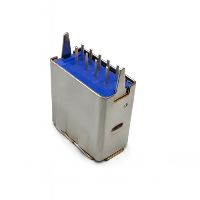
- RJ45 Jack + USB ConnectorRJ45 Jack + USB Connector
- RJ45 Jack Multi-Port (1x5 Port)RJ45 Jack Multi-Port (1×5 Port)
- Magnetic JacksMagnetic Jacks | RJ45 with Integrated Magnetics
- 10/100 BASE-T RJ45 Jack10/100 BASE-T RJ45 Jack
- 10/100 BASE-T RJ45 Jack +1000Base-T RJ4510/100 BASE-T RJ45 Jack +1000Base-T RJ45
- 10/100 BASE-T RJ45 Jack +USB Connector10/100 BASE-T RJ45 Jack +USB Connector
- 10/100 BASE-T RJ45 Jack Single Port (1x1 Port)10/100 BASE-T RJ45 Jack Single Port (1×1 Port)
- 10/100 BASE-T RJ45 Jack Dual Port (1x2 Port)10/100 BASE-T RJ45 Jack Dual Port (1×2 Port)
- 10/100 BASE-T RJ45 Jack Multi-Port (1x3 Port)10/100 BASE-T RJ45 Jack Multi-Port (1×3 Port)
- 10/100 BASE-T RJ45 Jack Multi-Port (1x4 Port)10/100 BASE-T RJ45 Jack Multi-Port (1×4 Port)
- 10/100 BASE-T RJ45 Jack Stacked ( 2x1 Port)10/100 BASE-T RJ45 Jack Stracked ( 2×1 Port)
- 10/100 BASE-T RJ45 Jack Stacked (2x2 Port)10/100 BASE-T RJ45 Jack Stracked (2×2 Port)
- 10/100 BASE-T RJ45 Jack Stacked ( 2x4 Port)10/100 BASE-T RJ45 Jack Stracked ( 2×4 Port)
- 10/100 BASE-T RJ45 Jack Stacked ( 2x6 Port)10/100 BASE-T RJ45 Jack Stracked ( 2×6 Port)
- 10/100 BASE-T RJ45 Jack Stacked ( 2x8 Port)10/100 BASE-T RJ45 Jack Stracked ( 2×8 Port)
- 1000 BASE-T RJ45 Jack1000 BASE-T RJ45 Jack
- 1000 BASE-T RJ45 Jack +USB Connector1000 BASE-T RJ45 Jack +USB Connector
- 1000 BASE-T RJ45 Jack Single Port (1x1 Port)1000 BASE-T RJ45 Jack Single Port (1×1 Port)
- 1000 BASE-T RJ45 Jack Dual Port (1x2 Port)1000 BASE-T RJ45 Jack Dual Port (1×2 Port)
- 1000 BASE-T RJ45 Jack Multi-Port (1x3 Port)1000 BASE-T RJ45 Jack Multi-Port (1×3 Port)
- 1000 BASE-T RJ45 Jack Multi-Port (1x4 Port)1000 BASE-T RJ45 Jack Multi-Port (1×4 Port)
- 1000 BASE-T RJ45 Jack Stacked ( 2x1 Port)1000 BASE-T RJ45 Jack Stracked ( 2×1 Port)
- 1000 BASE-T RJ45 Jack Stacked (2x2 Port)1000 BASE-T RJ45 Jack Stracked (2×2 Port)
- 1000 BASE-T RJ45 Jack Stacked ( 2x4 Port)1000 BASE-T RJ45 Jack Stracked ( 2×4 Port)
- 1000 BASE-T RJ45 Jack Stacked ( 2x6 Port)1000 BASE-T RJ45 Jack Stracked ( 2×6 Port)
- 1000 BASE-T RJ45 Jack Stacked ( 2x8 Port)1000 BASE-T RJ45 Jack Stracked ( 2×8 Port)
- 2.5G Base-T RJ45 Jack2.5G Base-T RJ45 Jack
- 2.5G BASE-T RJ45 Jack +USB Connector2.5G BASE-T RJ45 Jack +USB Connector
- 2.5G BASE-T RJ45 Jack Single Port (1x1 Port)2.5G BASE-T RJ45 Jack Single Port (1×1 Port)
- 2.5G BASE-T RJ45 Jack Dual Port (1x2 Port)2.5G BASE-T RJ45 Jack Dual Port (1×2 Port)
- 2.5G BASE-T RJ45 Jack Multi-Port (1x3 Port)2.5G BASE-T RJ45 Jack Multi-Port (1×3 Port)
- 2.5G BASE-T RJ45 Jack Multi-Port (1x4 Port)2.5G BASE-T RJ45 Jack Multi-Port (1×4 Port)
- 2.5G BASE-T RJ45 Jack Stacked ( 2x1 Port)2.5G BASE-T RJ45 Jack Stracked ( 2×1 Port)
- 2.5G BASE-T RJ45 Jack Stacked (2x2 Port)2.5G BASE-T RJ45 Jack Stracked (2×2 Port)
- 2.5G BASE-T RJ45 Jack Stacked ( 2x4 Port)2.5G BASE-T RJ45 Jack Stracked ( 2×4 Port)
- 2.5G BASE-T RJ45 Jack Stacked ( 2x6 Port)2.5G BASE-T RJ45 Jack Stracked ( 2×6 Port)
- 2.5G BASE-T RJ45 Jack Stacked ( 2x8 Port)2.5G BASE-T RJ45 Jack Stracked ( 2×8 Port)
- 5G Base-T RJ45 Jack5G Base-T RJ45 Jack
- 5G BASE-T RJ45 Jack +USB Connector5G BASE-T RJ45 Jack +USB Connector
- 5G BASE-T RJ45 Jack Single Port (1x1 Port)5G BASE-T RJ45 Jack Single Port (1×1 Port)
- 5G BASE-T RJ45 Jack Dual Port (1x2 Port)5G BASE-T RJ45 Jack Dual Port (1×2 Port)
- 5G BASE-T RJ45 Jack Multi-Port (1x3 Port)5G BASE-T RJ45 Jack Multi-Port (1×3 Port)
- 5G BASE-T RJ45 Jack Multi-Port (1x4 Port)5G BASE-T RJ45 Jack Multi-Port (1×4 Port)
- 5G BASE-T RJ45 Jack Stacked ( 2x1 Port)5G BASE-T RJ45 Jack Stracked ( 2×1 Port)
- 5G BASE-T RJ45 Jack Stacked (2x2 Port)5G BASE-T RJ45 Jack Stracked (2×2 Port)
- 5G BASE-T RJ45 Jack Stacked ( 2x4 Port)5G BASE-T RJ45 Jack Stracked ( 2×4 Port)
- 5G BASE-T RJ45 Jack Stacked ( 2x6 Port)5G BASE-T RJ45 Jack Stracked ( 2×6 Port)
- 5G BASE-T RJ45 Jack Stacked ( 2x8 Port)5G BASE-T RJ45 Jack Stracked ( 2×8 Port)
- 10G Base-T RJ45 Jack10G Base-T RJ45 Jack
- 10G BASE-T RJ45 Jack +USB Connector10G BASE-T RJ45 Jack +USB Connector
- 10G BASE-T RJ45 Jack Single Port (1x1 Port)10G BASE-T RJ45 Jack Single Port (1×1 Port)
- 10G BASE-T RJ45 Jack Dual Port (1x2 Port)10G BASE-T RJ45 Jack Dual Port (1×2 Port)
- 10G BASE-T RJ45 Jack Multi-Port (1x3 Port)10G BASE-T RJ45 Jack Multi-Port (1×3 Port)
- 10G BASE-T RJ45 Jack Multi-Port (1x4 Port)10G BASE-T RJ45 Jack Multi-Port (1×4 Port)
- 10G BASE-T RJ45 Jack Stacked ( 2x1 Port)10G BASE-T RJ45 Jack Stracked ( 2×1 Port)
- 10G BASE-T RJ45 Jack Stacked (2x2 Port)10G BASE-T RJ45 Jack Stracked (2×2 Port)
- 10G BASE-T RJ45 Jack Stacked ( 2x4 Port)10G BASE-T RJ45 Jack Stracked ( 2×4 Port)
- 10G BASE-T RJ45 Jack Stacked ( 2x6 Port)10G BASE-T RJ45 Jack Stracked ( 2×6 Port)
- 10G BASE-T RJ45 Jack Stacked ( 2x8 Port)10G BASE-T RJ45 Jack Stracked ( 2×8 Port)
- 10/100 BASE-T RJ45 Jack10/100 BASE-T RJ45 Jack
- Lan TransformerLan Transformer
- 10/100 BASE-T Lan Transformer10/100 BASE-T Lan Transformer
- 100/1000 Base-T Lan Transformer Single Port (1 Port)10/100 Base-T Lan Transformer Single Port (1 Port)
- 10/100 Base-T Lan Transformer Dual Port (2 Ports)10/100 Base-T Lan Transformer Dual Port (2 Ports)
- 100/1000 Base-T Lan Transformer Quad Port (4 Ports)10/100 Base-T Lan Transformer Quad Port (4 Ports)
- 1000 BASE-T Lan Transformer1000 BASE-T Lan Transformer
- 2.5G BASE-T Lan Transformer2.5G BASE-T Lan Transformer
- 5G BASE-T Lan Transformer5G BASE-T Lan Transformer
- 10G BASE-T Lan Transformer10G BASE-T Lan Transformer
- High Isolation Lan TransformerHigh Isolation Lan Transformer
- High Isolation Lan Transformer Single Port (1 Port)High Isolation Lan Transformer Single Port (1 Port)
- High Isolation Lan Transformer Dual Port (2 Ports)High Isolation Lan Transformer Dual Port (2 Ports)
- High Isolation Lan Transformer Quad Port (4 Ports)High Isolation Lan Transformer Quad Port (4 Ports)
- 10/100 BASE-T Lan Transformer10/100 BASE-T Lan Transformer
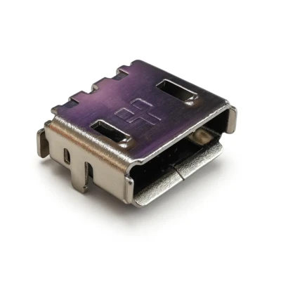
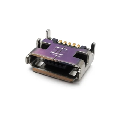
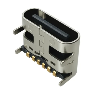
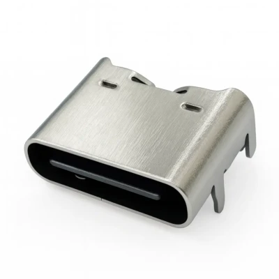
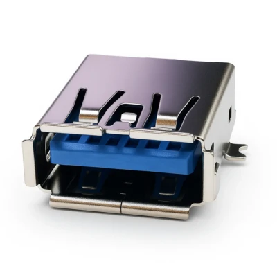
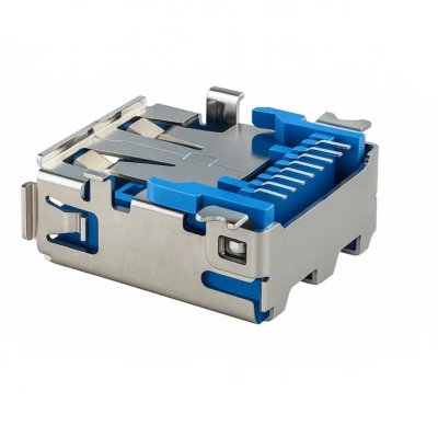
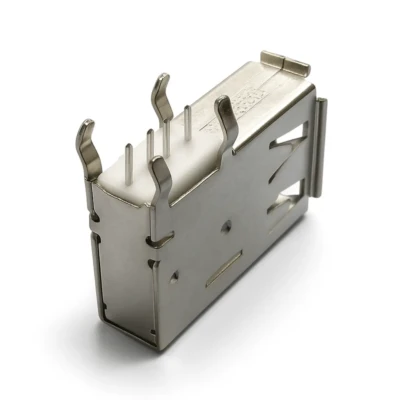
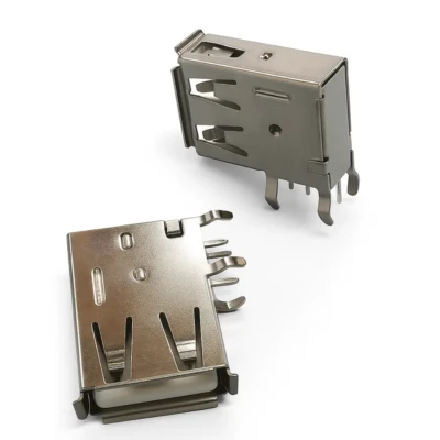
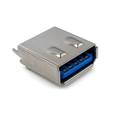
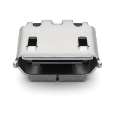
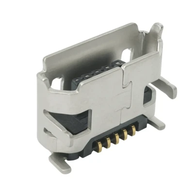
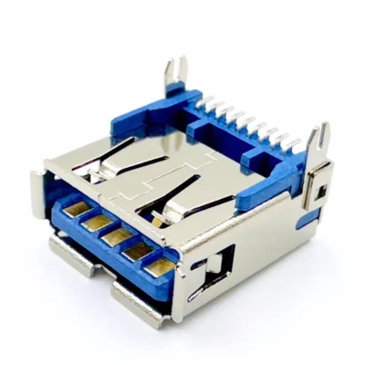
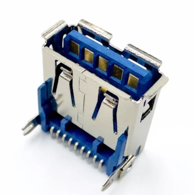
- USB ConnectorsUSB Connector
- Pin Headers and Socket HeadersPin Headers and Socket Headers
- FPC ConnectorsFPC Connectors
- Wire to board (WTB) connectorsWire to board (WTB) connectors
- SwitchesSwitches
- Battery connectorsBattery connectors
- OBD II connectorsOBD II connectors
- Stereo JackStereo Jack
- DC Power JackDC Power Jack
- Card ConnectorsCard Connectors
- CablesCables
- HDMI ConnectorsHDMI Connectors
- SPF/QSFP CaseSPF/QSFP Case
- Waterproof connectorsWaterproof connectors
- RJ11/RJ12 Modular JackRJ11/RJ12 Modular Jack
- OthersOthers
- RJ45 Jacks (Without Magnetics)RJ45 Jacks (Without Magnetics)
- Industries & Applications
- Resources
- Audio & VideoAudio & Video
- BlogDiscover our handpicked collection of blogs, reports, and resources spotlighting the latest industry trends fueling technological advancements. To stay ahead of the curve, bookmark this page and revisit often—we continuously refresh our content with cutting-edge innovations and market-shaping developments. Dive deeper into your sector of interest by clicking “View Full Collection” in each section to access our comprehensive library of insights.
- Case StudiesCase Studies
- DocumentationDocumentation
- FAQ & Help CenterFAQ & Help Center
- Featured SeriesFeatured Series
- GlossaryGlossary
- Latest ResourcesLatest Resources
- NewsNews
- SolutionSolution
- About Us
-
-
About Us
DW is a trusted provider of ICT products and solutions to enterprise customers worldwide.
-
-
-
Contact Us
info@dw-tek.com
86-769-82866368
- Contact Us
- Track Your Order
-

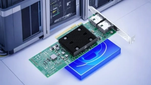
Dragon Well Data Center Cabling Solutions
-